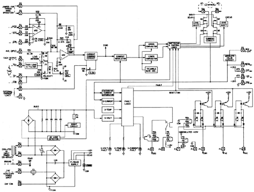
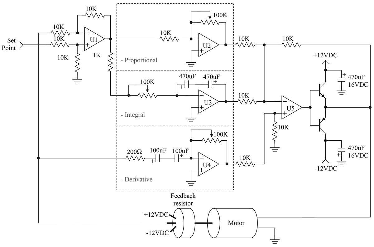
Ac Servo Motor Driver Circuit Diagram


A servo motor controller is a circuit that is used to control the position of a servo motor. It is also called as a servo motor driver. A servo motor controller consists of a controller, the servo motor and the power supply unit.Servo motor driver may be used to control a single servo or even a group of. In many projects where servo motor controlling is the mainstay of the task to be accomplished, the controller must drive more than one servo. An example of this is an RC airplane, which uses many servos. Essential Components • A micro-controller • A power supply unit Miscellaneous Components • A • Connectors, wires etc.
Micro-controller A servo motor is driven by applying the signal to it regular intervals. The servo is sensitive to timing variations. A pulse of specific width has to be applied at specific intervals of time. Typically, the duration of pulse varies from 0ms to 2.2ms and the repetition rate is 50Hz to 60Hz. For precise position control, the controller that is chosen must have timers that have the required resolution. Also, if more than one motor has to be controlled simultaneously, the processor clock must be fast enough. For a single motor control, an 8051 can be used like a AT89s51 or a P89v51RD2. Frankie J The One Zip.
Trolled and pulse width modulated DC servo motors drives were discussed in. Drive has been on economic grounds and its lower starting torque compared. 6.1 A single phase circuit diagram of an AC induction motor. 6.2 Reduced circuit resistance and inductance diagram. 6 AC Servo Motors. From SPWM can control brushless AC servo motor more easily and accurately. Three-phase Brushless AC motor driver. The driver circuit is required to drive the three-phase brushless AC motor. Hrd Keygen Generator. This can be done using three wired line, where sine wave. The SPWM wave generation schematic diagram. Table of part numbers and option. 1.1 Basic Specifications of Servo Drive For. Full Function. 1.2 Basic Specifications of Servo Drive for pulse type. 1.3 Control circuit. 1.4 Dimensions of drive. 1.5 Composition of peripheral equipments. 2.1 Model of AC Servo Motor. 50W(Low Inertia, Small Capacity).
But for more than one motor, we must use a PIC, like a PIC18F or a ATMEGA, so that it’s internal PWM can be utilized. However, the selection of micro-controller depends totally on the designer and the project requirements.
Power Supply The design of the power supply unit servo motor controller depends on the number of servo motors that are interfaced to the board. Download Halo 2 For Windows 7 Compressed Bootmgr. Servo motors operate from 4.8V to a 6V supply voltage. The typical value is 5V. Applying voltages greater than the supply voltage is not advisable as it may render the motor permanently useless. The current draw of the motor is variable and depends on the torque that it generates. Also it will draw less current when in idle mode and more current when it is running. A servo motors maximum current draw is given as its stall current.